Mine Hoisting In Deep Shafts In The 1st Half Of 21st Century
Mine Hoisting In Deep Shafts In The 1st Half Of 21st Century
Alfred Carbogno 1
Ťažné zariadenia v hlbokých šachtách v prvej polovici 21 storočia
V príspevku sú uvedené všeobecne informácie o hlbokých šachtách prevádzkovaných v Juhoafrickej republike. Príspevok sa tiež venuje opisu možností riešenia zvislej dopravy v šachtách hĺbky do 4300 m. Uvedené sú aj rôzne druhy používaných ťažných strojov, pričom pozornosť je venovaná ťažným strojom typu Blaira. Opísané sú jednotlivé problémy vyplývajúce z používania dlhých ťažných lán (ich konštrukcie, nosnosti) a používaní dopravný zariadeniach.
Key words: deep shaft, mine hosting, Blair winder, rope safety factor, drum sizing, skip factor
Introduction
The mineral deposits are exploited on deeper and deeper levels. In connection with this, definitions like “deep level” and “deep shaft” became more and more popular. These definitions concern the depth where special rules regarding an excavation driving, exploitation, rock pressure control, lining construction, ventilation, underground and vertical transport, work organization and economics apply.
It has pointed out that the “deep level” is a very relative definition and should be used only with a reference to particular hydro-geological, mining and technical conditions in a mine or coal-field. It should be also strictly defined what area of “deep level” or “deep shaft” definitions are considered. It can be for example:
- mining geo-engineering,
- technology of excavation driving,
- ventilation (temperature).
It is obvious that the “deep level” defined from one point of view, not necessarily means a “deep level” in another area. According to [5] as a deep mine we can treat each mine if:
- the depth is higher than 2300 m or
- mineral deposit temperature is higher than 38 ºC.
It is well known that the most of deep mines are in South Africa. Usually, they are gold or diamonds mines.
Economic deposits of gold-bearing ore are known to exist at depths up to 5000 m in a number of South Africa regions. However, due to the depth and structure of the reef in some areas, previous methods of reaching deeper reefs using sub-vertical shaft systems would not be economically viable. Thus, the local mining industry is actively investigating new techniques for a single-lift shaft up to 3500 m deep in the near future and probably around 5000 m afterwards. When compared with the maximum length of wind currently in operation of 2500 m, it is apparent that some significant innovations will be required.
The most important matter in the deep mine is the vertical transport and the mine hoisting used in the shaft. From the literature [1-12] results that B.M.R. (Blair Multi-Rope) hoist is preferred to be used in deep mines in South Africa. From the economic point of view, the most important factors are:
- construction and parameters of winding ropes (safety factor, mainly),
- mine hoisting drums capacity,
- low empty mass of the skip (the skip factor ”S”).
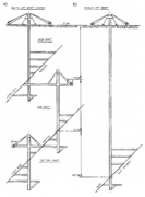
This article of informative character presents shortly above-mentioned problems based on the literature data [1-12]. Especially, the paper written by M.E. Greenway is very interesting [3]. From two transport systems used in the deep shaft, sub-vertical and the single-lift shaft systems, the second one is currently preferred. (Fig.1.) [6]
Hoisting Installation
The friction hoist (up to 2100 m), single drum and the double drum (classic and Blair type double drum) hoist are used in deep shafts in South Africa.
1 Dr. Ing. Alfred Carbogno, Silesian Technical University, Mining Mechanization Institute, Akademicka 2, PL 44-101 Gliwice, Poland
(Reviewed, revised version received August 5, 2002)
 Fig 1
Fig 1 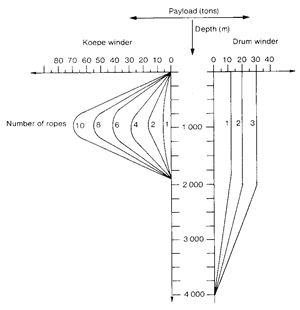 Fig 2
Fig 2Drum winders are most widely used in South Africa and probably in the world. Three types of winders fall into this category
- Single drum winders,
- Double drum winders,
- Blair multi-rope winders (BMR).
Double drum winders
Two drums are used on a single shaft, with the ropes coiled in opposite directions with the conveyances balancing each other. One or both drums are clutched to the shaft enabling the relative shaft position of the conveyances to be changed and permitting the balanced hoisting from multiple levels
The Blair Multi-Rope System (BMR)
In 1957 Robert Blair introduced a system whereby the advantage of the drum winder could be extended to two or more ropes. The two-rope system developed incorporated a two-compartment drum with a rope per compartment and two ropes attached to a single conveyance. He also developed a rope tension-compensating pulley to be attached to the conveyance. The Department of Mines allowed the statutory factor of safety for hoisting minerals to be 4,275 instead of 4,5 provided the capacity factor in either rope did not fall below the statutory factor of 9. This necessitated the use of some form of compensation to ensure an equitable distribution of load between the two ropes. Because the pulley compensation is limited, Blair also developed a device to detect the miscalling on the drum, as this could cause the ropes to move at different speeds and so affect their load sharing capability. Fig.2 shows the depth payload characteristics of double drum, BMR and Koepe winders.
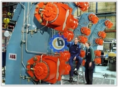
The B.M.R. hoist is used almost exclusively in South Africa, probably because they were invented there, particularly for the deep shaft use. There is one installation in England. Because of this hoist's physical characteristics, and South African mining rules favouring it in one respect, they are used mostly for the deep shaft mineral hoisting. The drum diameters are smaller than that of an equivalent conventional hoist, so one advantage is that they are more easily taken underground for sub-shaft installations.
A Blair hoist is essentially a conventional hoist with wider drums, each drum having a centre flange that enables it to coil two ropes attached to a skip via two headsheaves. The skip connection has a balance wheel, similar to a large multi-groove V-belt sheave, to allow moderate rope length changes during winding. A modification of this feature at one installation has the ropes fixed to the skip, and the headsheaves sitting on pistons with hydraulic cylinders interconnected. The sheaves can raise or lower to equalize rope tensions.
The Blair hoist's physical advantage is that the drum diameter can be smaller than usual and, with two ropes to handle the load, each rope can be much smaller. The government mining regulations permit a 5 % lower safety factor at the sheave for mineral hoisting with Blair hoists. This came about from a demonstration by the inventor, Robert Blair, that had one rope severed, at full speed, with the remaining rope holding the load. This 5 % permits the Blair hoists to go a little deeper than the other do.
On the other hand, the mining regulations require a detaching hook above the cage for man hoisting. The balance wheel does not suit detaching hooks, so a rope-cutting device was invented to cut the ropes off for a severe overwind. This was tested successfully but the Blair is not used for man winding on a regular basis.
The B.M.R. hoist has been built in three general styles similar to conventional hoists. The three styles are (Fig. 3 and 4):
- Tandem with one drum offset, to get the best fleet angle; these are called the „geared” type,
- In-line; or standard, direct-driven types only,
- Gearless; can be tandem or approximately in-line or inclined; with no mechanical connection between drums.
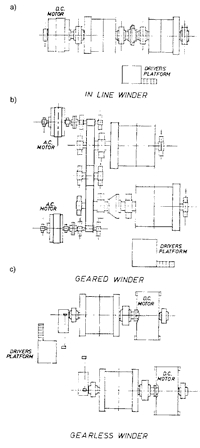 Fig 3
Fig 3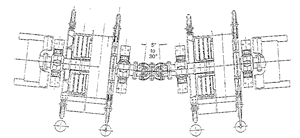 Fig 4
Fig 4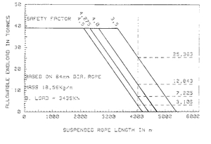 Fig 5
Fig 5The gearless B.M.R. hoist at East Dreifontein looks similar to an in-line hoist except that the drums are joined mechanically and they are a little out of line with each other. This is because each drum directly faces its own sheaves for the best fleet angle. The two hoist motors are fed via thyristor rectifier/inverter units from a common 6.6-KV busbar. The motors are thus coupled electrically so that the skips in the shaft run in balance, similar to a conventional double-drum hoist. Each motor alternates its action as a DC generator or DC motor, either feeding in or taking out energy from the system. The gearless Blair can be recognized by the offset drums and the four brake units. A second brake is always a requirement, each drum must have two brakes, because the two drums have no mechanical connection to each other. Most recent large B.M.R. hoists are 4,27 or 4,57 m in diameter, with 44,5 ÷ 47,6 mm ropes [1].
In arriving at a drum size the following parameters have been used:
- The rope to be coiled in four layers,
- The rope tread pressure at the maximum static tension to be less than 3,2 MPa,
- The drum to rope diameter ratio (D/d) to be greater than 127 to allow for a rope speed of 20 m/s.
With the above and a need to limit the axial length of the drums, a rope compartment of 8,5 m diameter by 2,8 m wide, was chosen. The use of 5 layers of coiled rope could reduce the rope compartment width to 2,15 m but this option has been discarded at this stage because of possible detrimental effects on the rope life. While the drum diameter could be reduced slightly to values dictated by the rope tread pressure and the D/d ratio; this would have resulted in an increased rum width and axial length of the winder.
One problem often associated with twin rope drum hoists is the rope fleeting angle. The axial length of the twin rope compartment drums requires wide centres for the headgear sheaves and conveyances in the shaft. To limit the diameter of the shaft, the arrangement illustrated in Fig. 4 has been developed and used on a hoist still to be installed. Here, an universal coupling or Hooke’s Joint has been placed between the two drums to allow the drums to be inclined towards the shaft center and so alleviate rope fleeting angle problem, even with sheave wheels at closer centres [11].
The rope safety factor
The graphs in Fig. 5 illustrate the endload advantage with reducing static rope safety factors. While serving their purpose very well over the years, the static safety factor itself must now be questioned. Static safety factors, while specifically relating to the static load in the rope were in fact established to take account of:
a. Dynamic rope loads applied during the normal winding cycle, particularly during loading, pull-away, acceleration, retardation and stopping,
b. Dynamic rope loads during emergency braking,
c. Rope deterioration in service particularly where this is of an unexpected or unforeseen nature.
Based on the static rope safety factor of 4, the rope endload of 12843 kg per rope can be achieved. With twin ropes, this amounts to an endload of 25686 kg. With a conveyance based on 40 % of payload of 18347 kg with a conveyance of 7339 kg. There are hoisting ropes of steel wires strength up to Rm = 2300 MPa (Rm up to 2600 MPa [6] is foreseen) used in deep shafts. There are also uniform strength hoisting ropes projected [2,8].
Conveyances
The winding machines made from a light alloy are used in hoisting installations in deep shafts. The skip factor (S) has been defined as the ratio of empty mass of the skip (including ancillary equipment such as rope attachments, guide rollers, etc) to the payload mass. If the rope end load is kept constant, a lower skip factor implies a larger payload – in other words, a more efficient skip from a functional point of view. However, the higher the payload for the same rope end load, the larger the out-of-balance load –implying a more winder power going hand in hand with the higher hoisting capacity. If, on the other hand, the payload is fixed, a lower skip factor implies a lower end load and a smaller rope-breaking load requirement. Under these conditions, an out-of-balance load attributable to the payload would remain the same, but that due to the rope would reduce slightly. The sensitivity of depth of wind and hoisting capacity to skip the factor is illustrated in Fig. 6 and 7. A reduction of skip factor from 0,5 to 0,4 results in a depth gain of about 40 m for Blair winders and 50 m for single-rope winders. The increase of hoisting capacity for a reduction of skip factor by about 0,1 is about 10 %.
Typical values for the “skip factor” are about 0,6 for skips and about 0,75 for cages for men and material hoisting. Reducing skip factors to say about 0,5 is a tough design brief and the trade-offs between lightweight skips and maintainability and reliability soon become evident in service.
The weight can be readily reduced by omitting (or reducing in thickness) skip liner plates but this could reduce skip life by wear of structural plate leading to the high maintenance cost or more frequent maintenance to replace thinner liner plates. Similarly, if the structural mass is saved by reducing section sizes or changing the material from steel to aluminium for example, the structural reliability is generally reduced and the fatigue cracking becomes more efficient.
Some success has been achieved in operating large capacity all – aluminium skips with low skip factors but the capital cost is high and a very real hoisting capacity constrain must exist before the additional cost is warranted. It would appear that the depth and hoisting capacity improvements are better made by reducing the rope factor of safety and increasing the winding speed. The philosophy of the skip design should be to provide robust skips with reasonable skip factors in the range of 0,5 to 0,6 that can be hoisted safely and reliably at high speeds and that are tolerant to the shaft guide misalignment.
It should be noted that some unconventional skips have been proposed (but not yet built and tested) that could offer skip factors as low as 0,35.
 Fig 6
Fig 6 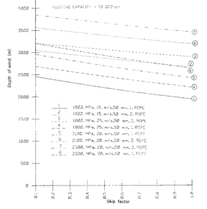 Fig 7
Fig 7Conclusions
The first installation of Blaire hoists took place in 1958. From that time we can observe a continuous development of this double-rope, double-drum hoists. Currently, they are used up to the depth of 3 150 m (man/material hoist at the Moab Khotsong Mine, to hoist 13 500 kg in a single lift, at 19,2 m/sec, using 2 x 7400 kW AC cyclo-convertor fed induction motors). The Blair Multi-Rope system can be use either during shaft sinking or during exploitation. The depth range for them is 715 -3150 m and the maximum skip load is 20 tons.
In South Africa in deep shafts single lift systems are preferred.
References
[1] BAKER. T.J.: New South African Drum Hoisting Plants. CIM Bulletin, No 752, December 1974, p. 86-96.
[2] CARBOGNO, A.: Winding Ropes of Uniform Strength. 1st International Conference LOADO 2001. Logistics and Transport. Hotel Permon, High Tatras, June 6th – 8th 2001 p.214-217.
[3] GREENWAY, M.E.: An Engineering Evaluation of the Limits to Hoisting from Great Depth. Int. Deep Mining Conference: Technical Challenges in Deep Level Mining, Johannesburg, SAIMM, 1990 p.449-481.
[4] HECKER, G.F.K.: The Safety of Hoisting Ropes in Deep Mine Shafts. International Deep Mining Conference: Technical Challenges in Deep Level Mining. Johannesburg, SAIMM, 1990 p. 831-838.
[5] HILL, F.G, MUDD J,B: Deep Level Mining in South African Gold Mines. 5th International mining Congress 1967, Moscow, p. 1 –20.
[6] LANE, N.M: Constraints on Deep-level Sinking – an Engineering Point of View. The Certificated Engineer, vol. 62, No6, December 1989/January 1991 p. 3-9.
[7] LAUBSCHER, P.S.: Rope Safety Factors for Drum Winders – Implications of the Proposed Amendments to the Regulations. Gencor Group, 1995 Shaft Safety Workshop. Midrand, Johannesburg, November 1995, paper No 5 p.1-11.
[8] MAC DONALD, D.H., PIENAAR, F.C.: State of the Art and Future Developments of Steel Wire Rope in Sinking and Permanent Winding Operations. Gencor Group, Shaft Safety Workshop Magaliesberg, 1994, paper No 13, p. 1-21.
[9] MCKENZIE, I.D.: Steel Wire Hoisting Ropes for Deep Shafts. International Deep Mining Conference: Technical Challenges in Deep Level Mining. Johannesburg, SAIMM, 1990 p. 839-844.
[10] SPARG, E.N.: Development of SA- Designed and Manufactured Mine Winders. The South African Mechanical Engineer vol.35, No 10, October 1985 p. 418-423.
[11] SPARG E,N.: Developments in Hoist Design Technology Applied to a 4000 m Deep Shaft. Mining Technology, No 886, June 1995, p. 179-184.
[12] SYKES, D.G., WIDLAKE, A.C.: Reducing Rope Factors of Safety for Winding in Deep Levels Shafts. International Deep Mining Conference. Technical Challenges in Deep Level Mining. Johannesburg, SAIMM, 1990 p. 819-829.
- Pre:ABB Mine Hoist System-Disc Brake
- Next:No
Tags: mine hoist, mine winder,mine shaft,mine winch,mine windlass